FEA ANALYSIS
FEA ANALYSIS
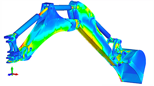
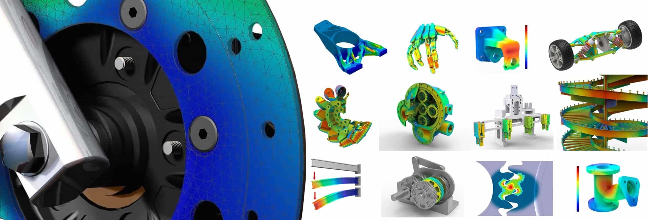
A FEA (Finite Element Analysis) is essential for solving complex technical problems. With a FEA analysis it is possible to make an accurate prediction of reality and calculate deformation, strength, stiffness and fatigue. This is an easier and cheaper alternative to purchasing a prototype. In addition, a FEA analysis software allows detailed visualizations of stresses and deformations.
HIGTEC offers the possibility to virtually test and predict the behavior of structures with a FEA analysis. Complex technical problems exposed to static or dynamic loads are calculated. The advantage of a FEA analysis is that we can perform stress and strain calculations that can normally be very challenging due to complex loads, geometries or material properties.
Advantages FEA analysis
- Faster to market, with less prototyping.
- Fast switching during the design phase.
- Optimize your design to reduce production costs.
- Develop in-depth product knowledge and quantify considerations.
- Stress-strain calculation of complex designs.
- Evaluating failures and limit risks
- Predict long-term problems such as creep and fatigue.
- Checking against existing standards or guidelines: EUROCODE/DNV/PED/ASME/EN13445/EN13480/ISO
Static FEA analysis
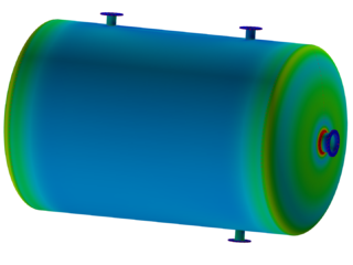
We can perform a linear or non-linear static FEA analysis for you. Your design is analyzed and its deformations are predicted using a finite element method. From the calculated displacement values it is possible to derive the stresses experienced by the body. The results allow us to evaluate whether your design has been deformed. We can also see if critical stress conditions occur in your design.


Dynamic FEA analysis
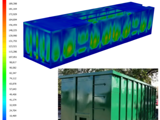
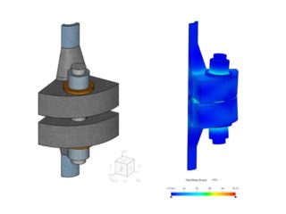
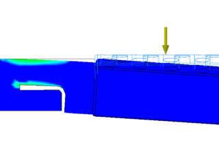
With a dynamic analysis we can analyze the behavior of a structure that is subject to time-dependent loads and displacements. In contrast to a static FEA analysis, inertia effects are taken into account. A dynamic FEA analysis provides the possibility to calculate impact loads and the resulting structural degradation. Similar to a static analysis, we can check for unwanted deformations or critical stresses. This way we can improve your design based on the results.
Modal FEA analysis
A FEA modal analysis can help determine the natural frequencies of a structure as a result of vibrations. The results are important parameters to understand and model structures exposed to dynamic loads. A harmonic analysis can show the peak response of a system under a load in a particular frequency range. The purpose of this is to determine the natural frequencies of a structure with the associated deformations during free vibration.

PRICE FEA ANALYSIS
BASIC ANALYSIS
starting at €250,-
 Analysis + Report
Linear Static
Linear Buckling
Normal Modes
Steady State Heat Transfer
PRO ANALYSIS
starting at €450,-
Analysis + Report
Linear Static
Linear Buckling
Impact Analysis
Normal Modes
Steady State Heat Transfer
ADVANCED ANALYSIS
starting at €850,-
Analysis + Report
Linear Static
Prestress Static
Linear Buckling
Impact Analysis
Normal Modes
Modal Frequency Response
Steady State Heat Transfer
CUSTOM ANALYSIS
on request
Analysis + Report
Non- linear Static
Non-linear Buckling
Dynamic Analysis
Multi- Axial Fatique
Vibration Fatique
Frequency/Transient Response
Transient Heat transfer
Impact Analysis
Shock/Response Spectrum
Finite element method
The finite element method is not a new technique; it was first introduced in the 1950’s (1950-1959) and has been continuously developed and improved since then. It has now become an extremely advanced tool for solving numerous technical problems. The finite element method is widely used and accepted in many branches of industry. The development of the FEM FEA analysis has made many other numerical analysis techniques and experimental test methods unnecessary.
In the automotive industry, for example, the structural coherence and performance of every new car design is thoroughly analyzed and evaluated with a FEA analysis. A simulation is used to analyze the strength of individual components and that of the car as a whole.
Aircraft and aerospace companies, like many other industries, rely on the finite element method in the same way. The efficient design of any modern aircraft is impossible without an FEA analysis. Many aircraft parts and therefore the complete machine are certified and receive airworthiness certificates through the results of a FEA analysis.
It is clear that the application possibilities and the potential of the finite element method are enormous. The growth of the finite element method is directly related to rapid advances in computer technology and computing power, especially in the last decade. As the power of computers has increased, it has become possible to analyze larger and more complex problems with the finite element method.
Complex stress, strain and deflection calculation
Engineers are faced with many questions when designing structures, including the following:
- Can this bridge support enough weight?
- Does my design meet the strength requirements?
- Which material should I use?
These questions can be answered by applying a finite element method. One of the reasons performing an FEA analysis helps engineers is that it allows them to predict performance. Instead of physically test every possible combination of materials and construction methods, engineers can simply have it done by a computer.
Performing an FEA analysis allows engineers to develop plans without worrying about testing them. It’s easier to visualize problems three-dimensionally and make changes while tracking results in real time.
An additional advantage of analysis is that it provides designers with valuable information related to safety. By simulating failure scenarios in advance, engineers can ensure that their design does not fail.
When do you use a FEA analysis?
A FEA analysis is applied when the design cannot be calculated analytically due to its complexity. It often happens that a design has complex geometries that cannot be calculated. A simulation must be performed, otherwise the analytical calculation will take too much time. In addition, simulations are performed to reduce production costs and reduce prototyping during the design phase.
Who uses a FEA analysis?
Many companies use finite element method software to optimize product designs. Sometimes companies hire consultancies to analyze designs and make recommendations based on the findings. These professionals include civil engineers, mechanical engineers, structural engineers, etc.
Industries that often use a FEA analysis are aerospace, automotive, chemical plants, pharmaceutical companies, shipbuilding, mechanical engineering, civil industry and water treatment companies. Government agencies also conduct extensive studies using a FEA analysis.
Advantages and disadvantages FEA analysis
There are advantages and disadvantages associated with performing a FEA analysis. The advantage is that you get results quickly. Engineers can instantly see how changing variables affect the overall results. In addition, a simulation saves costs through shorter development cycles.
A FEA analysis also has disadvantages. A FEA analysis only gives an approximation of reality and gives you an estimate of the stress distributions. The finite element method only works on mathematical approximations. Errors quickly occur that depend on factors such as material properties, boundary conditions and MESH refinement. Another disadvantage is that a simulation requires a lot of expertise and cannot be performed by everyone.
Static analysis applications
|
Aerospace Engineering |
Stress analysis of aircraft frames, wings, rockets and spacecraft components |
| Automotive Engineering |
Stress analysis of crankshaft, cylinder block, connecting rods, chassis |
| Biomedical Engineering |
Static analysis of bones, hip prostheses, teeth |
| Civil Engineering |
Analysis of dams, retaining walls, excavations; ground workers |
| Hydraulic Engineering |
Stress analysis of dams and hydraulic structures |
| Mechanical Engineering |
General one-, two- and three-dimensional and axisymmetric stress analyzes of components; analyzes of shafts, gears and pressure vessels; crack propagation |
| Nuclear engineering |
Static analysis of reactor vessels and structures |
| Construction technology |
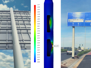
Static analysis of power pylons, girders and bridges |
Dynamic analysis applications
| Aerospace Engineering |
Dynamic analysis of aircraft and spacecraft components |
| Automotive Engineering |
Dynamic analysis of engine components, piston, disc brakes, exhaust; crash resistance of chassis |
| Biomedical Engineering |
Impact analysis of the skull; dynamic analysis of body and limb prosthesis |
| Civil Engineering |
Stress waves in rock structures |
| Mechanical Engineering |
impact problems; dynamic crack propagation |
| Nuclear Engineering |
Dynamic analysis of reactor components; shock spectrum analyses |
| Construction Technology |
Shock and earthquake analysis of buildings and bridges |
Modal analysis applications
| Aerospace Engineering | Frequency analysis of engine components, helicopter rotor blades, gearbox housing; acoustic analysis of passenger compartments of aircraft. |
| Automotive Engineering |
Acoustic analysis of passenger compartment and exhaust system; frequency analysis of gearbox housing and body |
| Biomedical Engineering |
Finite element analysis of bones, hip prostheses, teeth and heart |
| Hydraulic Engineering |
Natural periods of lakes and waters in ports |
| Electrical Engineering |
Circuit Board Natural Frequencies |
| Mechanical Engineering |
Natural frequency of components, axes; critical buckling loads |
| Nuclear Engineering |
distribution of neutron flux; frequency analysis of pressure vessels |
| Construction Technology |
Natural frequency and buckling loads of structures; vibration analysis of multi-storey buildings |